Optical Transceivers Classification
- Encapsulation types:GBIC, X2, XENPAK, SFP, XFP, SFP+, SFP28, QSFP, QSFP+, CFP, etc.
- Fiber Mode: Multimode fibers,Singlemode fibers
- Transmission Rate: 155M, 622M, 1.25G, 2.5G, 4.25G, 10G, 40G, 100G, 200G, 400G, etc.
- Wavelength: Conventional wavelength, CWDM, DWDM, etc.
- Connector Type: LC, SC, MPO, FC
Basic Principles of Optical Transceivers
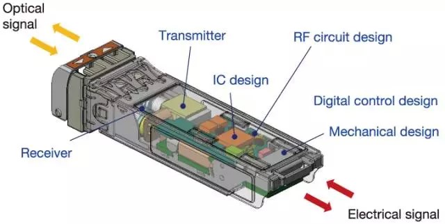
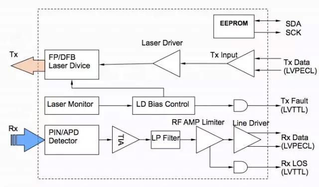
The optical transceiver module is the core device of optical communication, which completes the optical-electrical/electrical-optical conversion of optical signals. It consists of two parts: the receiving part and the transmitting part. The receiving part realizes the optical-electrical conversion, and the transmitting part realizes the electrical-optical conversion.
- Transmitting part:
The input electrical signal of a certain bit rate is processed by the internal driver chip to drive the semiconductor laser (LD) or light-emitting diode (LED) to emit a modulated optical signal of the corresponding rate. It has an automatic optical power control circuit (APC) inside to keep the output optical signal power stable.
- Receiving part:
After the optical signal of a certain bit rate is input into the module, it is converted into an electrical signal by the photodetection diode, and the electrical signal of the corresponding bit rate is output after the preamplifier. The output signal is generally PECL level. At the same time, an alarm signal will be output when the input optical power is less than a certain value.


Main parameters of optical transceivers
1. Transmission rate
Transmission rate refers to the number of bits transmitted per second, in Mb/s or Gb/s. Main rates: 155M, 1.25G, 2.5G, 4.25G, 10G, 25G 40G, 100G, 400G.
2. Transmission distance
The transmission distance of optical modules is divided into three types: short distance, medium distance and long distance. Generally speaking, 2km and below is short distance, 10-20km is medium distance, and 30km, 40km and above is long distance.
The transmission distance of the optical module is limited, mainly because there will be certain loss and dispersion when the optical signal is transmitted in the optical fiber.
3. Center wavelength
- The center wavelength refers to the optical band used for optical signal transmission. There are three main center wavelengths of commonly used optical modules: 850nm band, 1310nm band and 1550nm band.
- 850nm band: mostly used for short-distance transmission ≤ 2km
- 1310nm and 1550nm bands: mostly used for medium and long-distance transmission, transmission over 2km.
Fiber Type
1. Fiber Mode
According to the transmission mode of light in the fiber, the fiber can be divided into single-mode fiber and multi-mode fiber.
Multi-mode fiber (MMF) has a thicker core and can transmit multiple modes of light. However, its inter-mode dispersion is large, and the inter-mode dispersion will gradually increase with the increase of transmission distance.
Single-mode fiber (SMF) has a thin core and can only transmit one mode of light. Therefore, its inter-mode dispersion is very small and is suitable for long-distance communication.
2. End face and diameter of optical fiber
- According to the end face of the pin in the optical fiber connector: PC, SPC, UPC, APC
- According to the diameter of the optical fiber connector: Φ3, Φ2, Φ0.
3. Fiber optic interface connector types
Interface connectors are used to connect pluggable modules and corresponding transmission media.
Classification by optical fiber type:
Single-mode optical fiber connector (generally G.652 fiber: optical fiber inner diameter 9um, outer diameter 125um);
Multi-mode optical fiber connector (one is G.651 fiber with inner diameter 50um, outer diameter 125um; the other is inner diameter 62.5um, outer diameter 125um);
Classification by optical fiber connector connector type: FC, SC, ST, LC, MU, MTRJ, etc., currently commonly used are FC, SC, ST, LC
Interface parameters
Output optical power
Output optical power refers to the output optical power of the light source at the transmitting end of the optical module.
It can be understood as the intensity of light, in units of W or mW or dBm. W or mW is a linear unit, and dBm is a logarithmic unit. In communications, we usually use dBm to represent optical power.
Receiving sensitivity
Receiving sensitivity refers to the minimum receiving optical power of the optical module under a certain rate and bit error rate, unit: dBm. Generally speaking, the higher the rate, the worse the receiving sensitivity, that is, the greater the minimum receiving optical power, the higher the requirements for the receiving end device of the optical module.
Pressure sensitivity
Pressure sensitivity refers to the sensitivity value measured after the input signal is subjected to jitter and vertical eye closure degradation conditions, in dBm. This concept is only applicable to 10G interface modules (XENPAK modules and XFP modules).
Transmitted optical power and receiving sensitivity of optical modules
Transmitted optical power refers to the light intensity at the transmitting end, and receiving sensitivity refers to the light intensity that can be detected. Both are measured in dBm and are important parameters that affect the transmission distance. The transmission distance of the optical module is mainly limited by loss and dispersion.
The loss limit can be estimated according to the formula:
Loss-limited distance = (transmitted optical power-receiving sensitivity)/fiber attenuation
Saturation optical power value
Refers to the maximum optical power that can be detected at the receiving end of the optical module, which is generally -3dBm. When the received optical power is greater than the saturation optical power, it will also cause bit errors. Therefore, for optical modules with large transmitting optical power, bit errors will occur if no attenuation loopback test is performed.
Optical saturation
Also known as saturation optical power, it refers to the maximum input optical power when a certain bit error rate (10-10~10-12) is maintained at a certain transmission rate, unit: dBm.

